
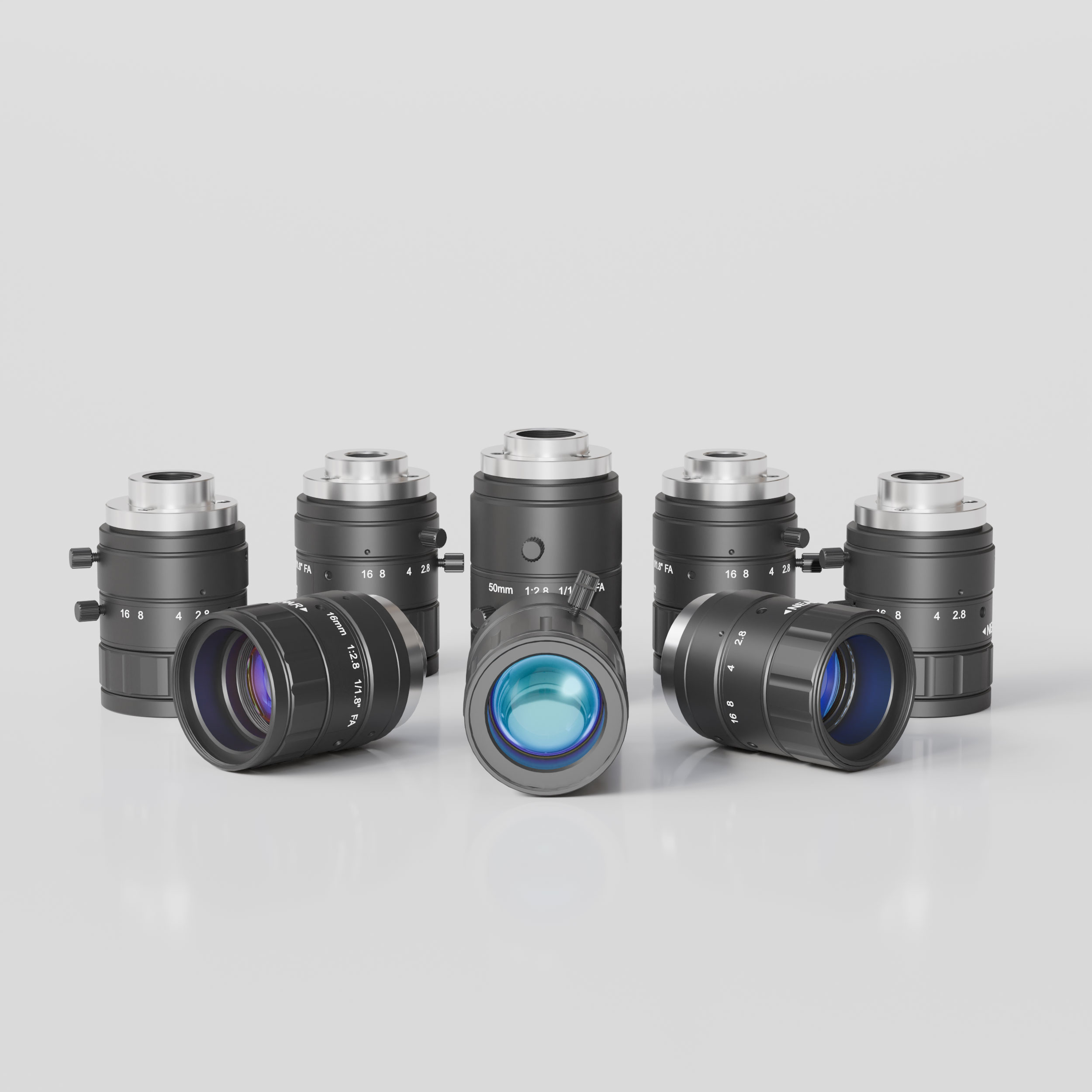
When choosing a C-Mount Lens, first confirm its mounting compatibility with the industrial camera. Next, check whether the lens matches the camera sensor. Then determine the required focal length based on the field of view, working distance, and sensor size. Finally, select the appropriate imaging performance for the inspection task.
The selection process follows four steps:
Mount Compatibility → Sensor Compatibility → Focal Length Selection → Imaging Performance
1. Confirm Mounting Compatibility Between the Industrial Camera and C-Mount Lens
The first step in choosing a C-Mount Lens is to confirm that it can be correctly installed on the industrial camera. Mount type, flange distance, and mechanical dimensions determine the mounting compatibility between the lens and camera.
① Lens Mount Type
The mount type determines whether the lens and industrial camera have compatible mechanical connections.
• C-Mount: Uses a 1-32 UN threaded mount, commonly found on industrial cameras and machine vision lenses.
• CS-Mount: Uses the same nominal thread specification as C-Mount.
• Mount Compatibility: Check the industrial camera's mount type and select a lens or mounting solution with matching mechanical specifications.
② Flange Distance
Flange distance is the designed distance between the lens mounting reference surface and the camera sensor's imaging plane.
• C-Mount: The standard flange distance is 17.526 mm.
• CS-Mount: The standard flange distance is 12.5 mm.
• Adapter Compatibility: Installing a C-Mount Lens on a CS-Mount camera typically requires a dedicated adapter to compensate for the 5.026 mm difference in flange distance.
For related mount conversion applications, refer to the CS-C Mount Adaptor Ring for Machine Vision Lens.
③ Mechanical Dimensions
Mechanical dimensions determine whether the C-Mount Lens fits within the available installation space around the industrial camera.
• Lens Diameter: Check the available clearance between the lens and surrounding lighting equipment, mounting brackets, and mechanical structures.
• Lens Length: Confirm that the total installed lens length meets the equipment's mechanical requirements.
• Adjustment Space: Allow sufficient space for focus adjustment, aperture controls, and locking screws.
2. Choose a C-Mount Lens Based on the Industrial Camera Sensor
After confirming mounting compatibility, evaluate the sensor coverage and resolution compatibility of the C-Mount Lens to ensure it meets the industrial camera's imaging requirements.
① Sensor Coverage
Sensor coverage is mainly evaluated using three specifications:
• Sensor Format: Identify the sensor format and actual active dimensions of the industrial camera sensor.
• Supported Sensor Format: Check the maximum sensor format supported by the C-Mount Lens and compare it with the camera sensor specifications.
• Image Circle: Ensure that the effective image circle diameter is at least as large as the sensor's active diagonal, so the entire sensor falls within the lens's supported imaging area.
② Resolution Compatibility
The resolving power of the lens must match the sampling capability of the industrial camera sensor.
• Camera Resolution: Check the camera's pixel count and image resolution. Higher camera resolution generally requires greater resolving power from the lens.
• Pixel Size: Check the physical size of each sensor pixel. Smaller pixels generally require the lens to maintain sufficient image quality at higher spatial frequencies.
• Lens Resolution: Based on the camera sensor's pixel size, review the manufacturer's MTF, lp/mm, or resolution specifications. Confirm that the lens provides sufficient resolving power at the required spatial frequencies, including image performance at both the center and edges of the imaging area.
3. Determine Focal Length Based on Field of View, Working Distance, and Sensor Size
To select the focal length of a C-Mount Lens, first determine the required imaging area and working distance. Then calculate the focal length using the effective dimensions of the camera sensor.
① Determine the Field of View
Determine the required field of view based on the object size and inspection area.
• Object Size: Measure the actual width and height of the object being inspected.
• Field of View: Define the area that must be captured in a single image, including sufficient margins for object movement or positioning.
② Determine the Working Distance
Determine the working distance based on the actual installation conditions of the industrial camera.
• Installation Distance: Measure the distance between the lens and the object under normal operating conditions.
• Focus Range: Ensure that this distance falls within the focusing range supported by the C-Mount Lens.
③ Calculate and Select the Focal Length
Use the effective camera sensor dimensions, field of view, and working distance to estimate the required focal length.
• Sensor Size: Identify the effective imaging width or height of the camera sensor.
• Focal Length Calculation: For conventional non-macro imaging applications, use the following approximate formula to estimate the focal length:
Focal Length ≈ (Sensor Width × Working Distance) ÷ Horizontal FOV
• Focal Length Selection: Use the calculated result to identify a suitable focal length, then check the manufacturer's actual field of view, working distance, and focusing range specifications. For close-range imaging, use the product's optical specifications to confirm the final focal length selection.
4. Choose C-Mount Lens Imaging Performance Based on the Inspection Task
After confirming mounting compatibility, sensor matching, and focal length, evaluate the aperture, depth of field, and distortion requirements of the C-Mount Lens according to the actual inspection task.
① Aperture
Aperture selection mainly depends on the industrial camera's lighting conditions and exposure requirements.
• F-number: A lower F-number corresponds to a larger aperture opening, allowing more light to enter the lens.
• Lighting Conditions: Select the aperture according to the available illumination intensity to provide sufficient image brightness for the inspection task.
• Exposure Time: For high-speed inspection requiring shorter exposure times, choose an appropriate aperture together with sufficient illumination to maintain the required image brightness and contrast.
② Depth of Field
Depth of field determines the range along the object's depth direction that remains sufficiently sharp.
• Required Depth Range: Determine the actual depth range over which the inspection object must remain acceptably sharp, from its nearest to farthest inspection position.
• Object Height Variation: Measure the height difference between the highest and lowest inspection areas, ensuring that the effective depth of field covers all required regions.
• Aperture Adjustment: Reducing the aperture opening generally increases depth of field. However, excessively small apertures increase diffraction effects, so depth of field and image sharpness must be balanced.
③ Distortion
Distortion requirements depend on the geometric accuracy required by the industrial camera's inspection task.
• Measurement: Based on the system's allowable dimensional measurement error, select a lens with suitable distortion specifications across the actual working field of view. Verify that the residual error after distortion correction meets the required measurement accuracy.
• Positioning: High-precision positioning requires control of coordinate deviations across different image positions to ensure that object locations meet the required positioning accuracy.
• Edge Detection: For contour and edge inspection, evaluate the lens distortion specifications against the required edge-position accuracy.